
Useful Info
Cidunt ut laoreet ater dolore atre magna aliquam inim atere hasel veniam, quis nostrud porta qmet queryten msiole aters.


2 Wire RTD
Why Use a 2 Wire RTD?
This is the simplest and least expensive configuration but also the most limiting. Using 2-wire RTDs provides fair temperature measurement when thereceiving device is connected directly to the sensor without the use of extension wire. The inherent resistance caused by using extension wires cannot be compensated when using a 2-wire configuration. Extension wires are also subjected to corrosion which may further degrade the reading.
When accuracy is not critical, a two-wire RTD is the least expensive; offering. Using lead wires to place any distance between a two wire RTD and a receiving device will further compromise its accuracy. The potential for poor accuracy from a two-wire RTD stems from its inability to compensate for lead length, resistance that changes the ohm value of the original signal. A two-wire RTD should be used only in applications where the receiving device connects directly to the sensor
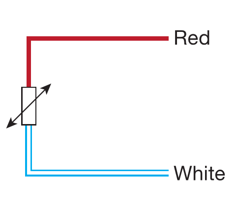
2 Wire RTD Color Code
Lead wire colors are defined in the IEC 60751-2008 standard where all wire colors are shown as in the following figure.
2 Wire RTD Wiring Diagram
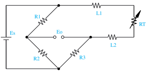
Shown is a 2-wire RTD connected to a typical Wheatstone bridge circuit. Es is the supply voltage; Eo is the output voltage; R1, R2, and R3 are fixed resistors; and RT is the RTD. In this uncompensatedcircuit, lead resistance L1 and L2 add directly to RT